Myself and 2 other teammates created a simulation to model gyroscopic precession, measuring and recording a real life gyroscope for comparison.
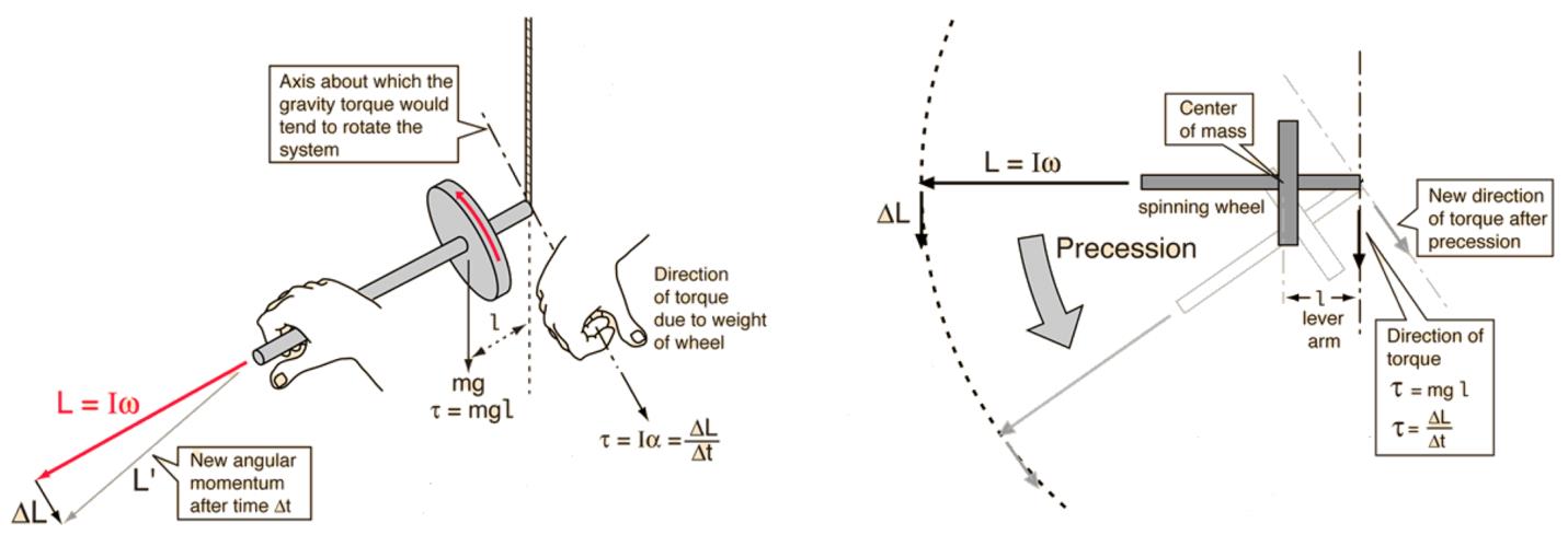
Precession is the process in which a rotating object undergoes a change in the orientation of the rotational axis of its rigid body. In the case of a gyroscope, precession results from a change in angular momentum caused by the gravitational torque applied onto the body. The direction of precession can be predicted based on the rotor’s rotational direction.

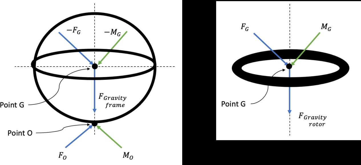
The gyroscope in question could be simulated as 2 separate rigid bodies modelled with 2 Newton-Euler vector equations, from which the reaction forces and moments can be expressed as a function of generalised coordinates.

As the equations of motion must not contain any unknown reaction forces or
moments, the four Newton-Euler vector equations previously found need to be
investigated in order to simulate the system. The NE equations are then decoupled to extract the EOM in terms of known parameters which can then be expressed in state space representation, allowing for numerical calculation via Matlab’s ode45 function.

The animation of the gyroscope is essential in visually assessing the success of the
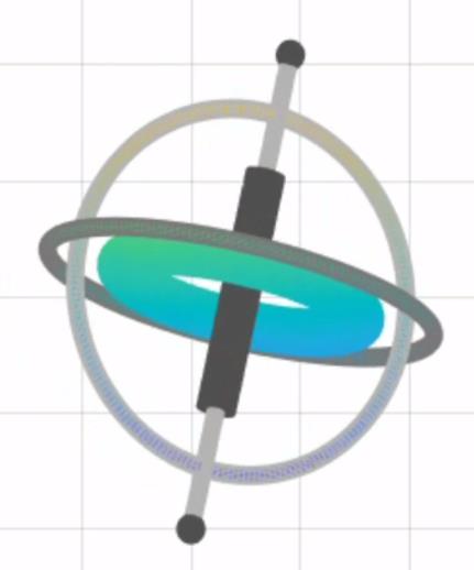
simulation. To animate the gyroscope it was first split into four pieces; a central cylinder, a vertical torus, a horizontal torus and a central torus. The central torus is the representation of the rotor and the other three pieces make up the gyroscope frame. The pieces were modelled in their respective frames, frame 3 for the frame and frame 4 for the rotor. Extra details about the shape of the frame were added so that the model looks more like the actual gyroscope. However these details only affect the displayed model and not the calculations involved in generating the animation.
For a loop spanning the display time, the state space variables for the angles are calculated each iteration. Alpha, beta, gamma and delta can then be subbed into the rotation matrices at that time frame. The rotor is then converted from frame 4 to 0 and the frame components from 3 to 0, via the rotation matrices. For each iteration the gyroscope is displayed in frame zero and appears to have a fluid motion.

In order to create a workable simulation this report made a number of significant assumptions that result in the differences between the simulated model and the experimental model. • Friction By the removal of friction from the analysis the discrepancy between the simulated animation and the filmed gyroscope grows significantly with time, although via setting similar initial conditions the initial behaviour of the two can be fairly accurate. The primary item of investigation in this report, the gyroscopic precession can be seen occur via both methods and can be tweaked to behave very similarly. • Imperfect Fitting As can be heard by the loud rattling in some of the video recordings attached, the gyroscope pieces have a degree of slip-room between the fittings, resulting in chaotic motion that strays from the ideal • Imperfect Surroundings The system would experience similar chaotic actions to those outlined above due to the supporting surface beneath being imperfect, with the base occasionally sliding along the table making the ’fixed’ reference frame less fixed than would be ideal
As can be seen in the opening video to this post, the model was fairly accurate during the initial period of simulation but non-ideal behaviour of the real-world gyroscope quickly creates asymmetries between itself and the MATLAB simulation. For those who would like to have a fiddle with our design please feel free to do so, I’d also love to hear from you if you have pointers or suggestions for future improvements.

Comments